Comnet CNGE2FE8MSPOE Technical Information
Browse online or download Technical Information for Networking Comnet CNGE2FE8MSPOE. Comnet CNGE2FE8MSPOE System information User Manual
- Page / 162
- Table of contents
- BOOKMARKS
- CNGE2FE8MSPOE 1
- FCC Warning 2
- CE Mark Warning 2
- Content 3
- Chapter 1 Introduction 8
- 1.2 Software Features 12
- 1.3 Package Contents 15
- 2.1 Physical Dimension 16
- 2.2 Front Panel 16
- 2.3 Top View 17
- 2.4 LED Indicators 18
- 3.1 Installation Steps 20
- 3.2 DIN-Rail Mounting 21
- 3.4 Wiring the Power Inputs 25
- 3.6 Cabling 27
- Transceiver Inserted 28
- Remove LC connector 30
- 4.1 X-Ring Application 33
- 4.3 Dual Homing Application 35
- Chapter 5 Console Management 36
- Console login interface 38
- 5.4 CLI Management 39
- 5.5 Commands Level 39
- 6.3 System Login 42
- 6.4 System Information 43
- 6.5 IP Configuration 44
- IP configuration interface 45
- 6.6 DHCP Server 46
- 6.6.1 System configuration 47
- 6.6.2 Client Entries 48
- 6.6.3 Port and IP Bindings 49
- 6.7 TFTP 50
- 6.7.2 Restore Configuration 51
- 6.7.3 Backup Configuration 52
- 6.8 System Event Log 53
- SMTP Configuration interface 56
- 6.9 Fault Relay Alarm 59
- 6.10 SNTP Configuration 60
- SNTP Configuration interface 63
- 6.11 IP Security 64
- IP Security interface 65
- 6.12 User Authentication 66
- 6.13 Port Statistics 67
- Port Statistics interface 68
- 6.14 Port Control 69
- Port Control interface 70
- 6.15 Port Trunk 71
- LACP disabled 73
- LACP enabled 75
- 6.15.3 State Activity 79
- State Activity of Switch 2 80
- 6.16 Port Mirroring 81
- 6.17 Rate Limiting 82
- 6.18 VLAN configuration 84
- 6.18.1 Port-based VLAN 85
- 6.18.2 802.1Q VLAN 88
- 802.1Q Configuration 89
- Group Configuration 91
- 6.19 Rapid Spanning Tree 93
- 6.19.2 Port Configuration 95
- 6.20 SNMP Configuration 97
- 6.20.2 Trap Configuration 99
- 6.20.3 SNMPV3 Configuration 100
- 6.21 QoS Configuration 103
- QoS Configuration interface 104
- 6.21.2 Port-based Priority 105
- 6.21.3 COS Configuration 105
- 6.21.4 TOS Configuration 105
- 6.22 IGMP Configuration 107
- IGMP Configuration interface 108
- 6.23 X-Ring 109
- X-ring Interface 110
- 6.24 LLDP Configuration 111
- 6.25.1 System Configuration 112
- 6.25.2 Port Configuration 114
- 6.25.3 Misc Configuration 116
- 6.26 MAC Address Table 117
- 6.26.2 MAC Filtering 119
- 6.26.3 All MAC Addresses 120
- 6.27 Power over Ethernet 123
- 6.28 Factory Default 125
- 6.29 Save Configuration 126
- 6.30 System Reboot 127
- Troubles shooting 128
- RJ45 Pin Assignments 129
- Cross over cable schematic 130
- Cross over cables schematic 132
- RJ45 Pin Assignment of PoE 133
- Appendix B—Command Sets 135
- Halt and perform a cold 136
- Port Commands Set 138
- Trunk Commands Set 141
- VLAN Commands Set 142
- Spanning Tree Commands Set 144
- QOS Commands Set 147
- IGMP Commands Set 147
- LLDP Commands Set 149
- SNMP Commands Set 150
- Port Mirroring Commands Set 152
- 802.1x Commands Set 153
- TFTP Commands Set 155
- SNTP Commands Set 159
- X-ring Commands Set 160
- PoE Commands Set 161
- Communication Networks 162
Summary of Contents
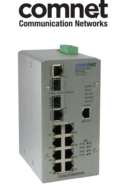
INSTALLATION AND OPERATION MANUAL CNGE2FE8MSPOE ENVIRONMENTALLY HARDENED MANAGED ETHERNET SWITCH WITH (8) 10/100TX + (2) 10/100/
3 Sensitivity: -36 to -32 dBm (Single mode); -34 to -30 dBm (Multi mode) PoE pin assignment RJ45 port # 1~# 8 support IEEE 802.3af End-point, Alterna
93 6.20.3 SNMPV3 Configuration Configure the SNMP V3 function. Context Table Configure SNMP v3 context table. Assign the context name of context t
94 SNMP V3 configuration interface Access Table Configure SNMP v3 access table. Context Prefix: set up the context name. Group Name: set up
95 MIBview Table Configure MIB view table. ViewName: set up the name. Sub-Oid Tree: fill the Sub OID. Type: select the type – exclude or in
96 6.21 QoS Configuration Quality of Service (QoS) is the ability to provide different priority to different applications, users or
97 QoS Configuration interface
98 6.21.2 Port-based Priority Configure the priority level for each port. With the drop-down selection item of Priority Type above being selected a
99 When the IP packet is received, the system will check the TOS level value in the IP packet that has received. For example, the user sets t
100 6.22 IGMP Configuration The Internet Group Management Protocol (IGMP) is an internal protocol of the Internet Protocol (IP) suite.
101 IGMP Configuration interface
102 6.23 X-Ring X-Ring provides a faster redundant recovery than Spanning Tree topology. The action is similar to STP or RSTP, but the
4 61000-4-4, CE EN61000-4-5, CE EN61000-4-6, CE EN61000-4-8, CE EN61000-4-11, CE EN61000-4-12, CE EN61000-6-2, CE EN61000-6-4 Safety UL, cUL, CE/EN
103 Enable Couple Ring string label. Couple Port: Assign the member port which is connected to the other ring group. Control Port: When the
104 6.24 LLDP Configuration Link Layer Discovery Protocol (LLDP) is defined in the IEEE 802.1AB, it is an emerging standard which pr
105 6.25 Security—802.1X/Radius Configuration 802.1x is an IEEE authentication specification which prevents the client from accessing a wireless ac
106 802.1x System Configuration interface
107 6.25.2 Port Configuration You can configure the 802.1x authentication state for each port. The state provides Disable, Accept, Reject, and Autho
108 802.1x Per Port Setting interface
109 6.25.3 Misc Configuration Quiet Period: Set the period which the port doesn’t try to acquire a supplicant. TX Period: Set the period
110 6.26 MAC Address Table Use the MAC address table to ensure the port security. 6.26.1 Static MAC Address You can add a static MAC address that
111 Static MAC Addresses interface
112 6.26.2 MAC Filtering By filtering MAC address, the switch can easily filter the pre-configured MAC address and reduce the un-safety. You can add
5 1.2 Software Features Management SNMP v1 v2c, v3/ Web/Telnet/CLI SNMP MIB RFC 1215 Trap, RFC1213 MIBII, RFC 1157 SNMP MIB, RFC 1493 Bridge MIB, R
113 6.26.3 All MAC Addresses You can view all of the MAC addresses learned by the selected port. Select the port number. The selected port of
114 6.26.4 MAC Address Table—Multicast Filtering Multicasts are similar to broadcasts, they are sent to all end stations on a LAN or VLA
115 Multicast Filtering interface
116 6.27 Power over Ethernet This segment shows the Power over Ethernet function. PoE Status Actual Power Consumption: This column shows the r
117 subtracted from the pre-capacitance voltage to get a charge rate. If this charge rate is within the window of the PD signatures, the device is co
118 6.28 Factory Default Reset switch to default configuration. Click to reset all configurations to the default value. Factory Default interf
119 6.29 Save Configuration Save all configurations that you have made in the system. To ensure the all configuration will be saved. Click to sa
120 6.30 System Reboot Reboot the switch in software reset. Click to reboot the system. System Reboot interface
121 Troubles shooting Verify that is using the right power cord/adapter (DC 24-48V), please don’t use the power adapter with DC out
122 Appendix A—RJ45 Pin Assignment RJ45 Pin Assignments The UTP/STP ports will automatically sense for Fast Ethernet (10Base-T/100Base-TX
6 Port Mirror Supports 3 mirroring types: “RX, TX and Both packet”. IGMP Supports IGMP snooping v1,v2 256 multicast groups and IGMP query IP Security
123 3 Transmit Data plus (TD+) Receive Data plus (RD+) 6 Transmit Data minus (TD-) Receive Data minus (RD-) 10/100Base-TX Cable Schematic The fo
124 10/100/1000Base-TX Cable Schematic Straight through cables schematic
125 Cross over cables schematic
126 RJ45 Pin Assignment of PoE With 100BASE-TX/10BASE-T cable, pins 1 and 2 are used for transmitting data, and pins 3 and 6 for receiving data; pin
127 Pin out of PoE Endspan Hub/Switch Pin Signal / Name 1 TX+/VCC+ 2 TX-/VCC+ 3 TX+/VCC- 4 5 6 TX-/VCC- 7 8 Note ‘+’ and ‘-‘ signs represent
128 Appendix B—Command Sets Commands Set List User EXEC E Privileged EXEC P Global configuration G VLAN database
129 [Ip-address] [Subnet-mask] [Gateway] address of switch 192.168.1.1 255.255.255.0 192.168.1.254 ip dhcp G Enable DHCP client function of switch s
130 [Hours] (in hour) leasetime 1 dhcpserver ipbinding [IP address] I Set static IP for DHCP clients by port switch(config)#interface fastEthernet 2
131 telnet server Port Commands Set Netstar Commands Level Description Example interface fastEthernet [Portid] G Choose the port for modification
132 bandwidth type all I Set interface ingress limit frame type to “accept all frame” switch(config)#interface fastEthernet 2 switch(config-if)#bandw
7 SNMP Trap 1. Cold start 2. Link up/down 3. X-Ring topology changed 4. Authorization fail 5. PD disconnect trap-PoE port event DHCP Provides DHCP
133 and zero means no limit. show bandwidth I Show interfaces bandwidth control switch(config)#interface fastEthernet 2 switch(config-if)#show bandwi
134 Trunk Commands Set Netstar Commands Level Description Example aggregator priority [1~65535] G Set port group system priority switch(config)#aggre
135 comma(ex.2, 3, 6) show aggregator P Show the information of trunk group switch#show aggregator 1 or switch#show aggregator 2 or switch#show aggre
136 port [PortNumbers] show vlan [GroupID] or show vlan V Show VLAN information switch(vlan)#show vlan 23 no vlan group [GroupID] V Delete port base
137 [PortNumber] trunk-link tag [TaggedVID List] VLAN by trunk group trunk-link tag 2,3,6,99 or switch(vlan)#vlan 8021q trunk 3 trunk-link tag 3-20 v
138 protocol data unit (BPDU) message from the root switch within this interval, it recomputed the Spanning Tree Protocol (STP) topology. spanning-tr
139 command to set the path cost for Spanning Tree Protocol (STP) calculations. In the event of a loop, spanning tree considers the path cost when se
140 interface. switch(config-if)#stp-admin-non-stp False show spanning-tree E Displays a summary of the spanning-tree states. switch>show s
141 igmp enable G Enable IGMP snooping function switch(config)#igmp enable Igmp query auto G Set IGMP query to auto mode switch(config)#igmp query au
142 LLDP Commands Set Netstar Commands Level Description Example lldp enable G Enable LLDP function switch(config)#lldp enable lldp interval [Time se
8 1.3 Package Contents Please refer to the package content list below to verify them against the checklist. 8 10/100TX + 2 10/100/1000T/Mini
143 no mac-address-table G Remove dynamic entry of MAC address table switch(config)#no mac-address-table SNMP Commands Set Netstar Commands Level
144 [Group Name] password [Authentication Password] [Privacy Password] Privacy password could be empty. snmpv3 access context-name [Context Name ]
145 [User Name] user of SNMPv3 agent. Test no snmpv3 access context-name [Context Name ] group [Group Name ] security-level [NoAuthNoPriv|AuthN
146 port of monitor function monitor tx [Port ID] G Set TX destination port of monitor function switch(config)#monitor tx 3 show monitor P Show port
147 8021x system accountport [port ID] G Use the 802.1x system account port global configuration command to change the accounting port switch(config
148 8021x misc servertimeout [sec.] G Use the 802.1x misc server timeout global configuration command to set the server timeout. Switch(config)#8021
149 backup flash:backup_cfg G Save configuration to TFTP and need to specify the IP of TFTP server and the file name of image. Switch(config)#backup
150 [IP address] server IP 192.168.1.5 smtp sender [sendername] G Configure sender of mail switch(config)#smtp snder [email protected] smtp authentication
151 Down|Both] switch(config-if)#event smtp both show event P Show event selection switch#show event no event device-cold-start G Disable cold start
152 SNTP Commands Set Netstar Commands Level Description Example sntp enable G Enable SNTP function switch(config)#sntp enable sntp daylight G Enable
9 Chapter 2 Hardware Description In this paragraph, it will describe the Industrial switch’s hardware spec, port, cabling information,
153 number sntp sync-interval [Secs] G Set synchronization interval switch(config)#sntp sync-interval 64 show sntp P Show SNTP information switch#sho
154 no ring couplering G Disable couple ring switch(config)# no ring couplering no ring dualhoming G Disable dual homing switch(config)# no ring dual
155 ComNet Customer Service Customer Care is ComNet Technology’s global service center, where our professional staff are ready to answer your que
10 2.3 Top View The top panel of the 8 10/100TX w/ X-Ring Managed Industrial Switch has one terminal block connector of two DC power
11 2.4 LED Indicators The diagnostic LEDs that provide real-time information of system and optional status are located on the front
12 (Lower LED) Off 10/100M On The SFP port is linking Blinks The port is transmitting or receiving packets from the TX device. Link/Active (P9, P10
FCC Warning This Equipment has been tested and found to comply with the limits for a Class-A digital device, pursuant to Part 15 of th
13 Chapter 3 Hardware Installation In this paragraph, we will describe how to install the 8 10/100TX w/ X-Ring Managed Industrial Swi
14 3.2 DIN-Rail Mounting The DIN-Rail is screwed on the industrial switch when out of factory. If the DIN-Rail is not screwed on the industrial swi
15
16 1. First, insert the top of DIN-Rail into the track. 2. Then, lightly push the DIN-Rail into the track. 3. Check if the DIN-Rail is tight
17 3.3 Wall Mount Plate Mounting Follow the steps below to mount the industrial switch with wall mount plate. 1. Remove the DIN-Rail from the
18 3.4 Wiring the Power Inputs Please follow the steps below to insert the power wire. 1. Insert DC power wires into the contacts 1 and 2 for po
19 3.5 Wiring the Fault Alarm Contact The fault alarm contacts are in the middle of the terminal block connector as the picture show
20 3.6 Cabling Use four twisted-pair, Category 5e or above cabling for RJ45 port connection. The cable between the switch and the li
21 To connect the transceiver and LC cable, please follow the steps shown below: First, insert the transceiver into the SFP module. Notice that th
22 LC connector to the transceiver
Content Chapter 1! Introduction ...1!1.1! Hardware Features ... 1!1.2! S
23 To remove the LC connector from the transceiver, please follow the steps shown below: First, press the upper side of the LC connector to release
24 Chapter 4 Network Application This chapter provides some sample applications to help user to have more actual idea of industrial switch f
25 The illustration below shows an example of power over Ethernet application.
26 4.1 X-Ring Application The industrial switch supports the X-Ring protocol that can help the network system to recovery from network
27 4.2 Coupling Ring Application In the network, it may have more than one X-Ring group. By using the coupling ring function, it can connect eac
28 4.3 Dual Homing Application Dual Homing function is to prevent the connection lose from between X-Ring group and upper level/core sw
29 Chapter 5 Console Management 5.1 Connecting to the Console Port The supplied cable which one end is RS-232 connector and the other
30 NC 7 Brown/White NC 8 Brown 5.3 Login in the Console Interface When the connection between Switch and PC is ready, turn on the PC a
31 Having finished the parameter settings, click ‘OK’. When the blank screen shows up, press Enter key to have the login prompt appears. Key
32 5.4 CLI Management The system supports the console management—CLI command. After you log in on to the system, you will see a command promp
5.2! Pin Assignment ... 29!5.3! Login in the Console Interface ... 30!5.4! CLI Management
33 EXEC mode. • Display advanced function status • Save configuration Global Configuration Enter the configure command while in privileged EXEC mode.
34 Chapter 6 Web-Based Management This section introduces the configuration and functions of the Web-Based management. 6.1 About Web-based Manage
35 6.3 System Login 1. Launch the Internet Explorer on the PC 2. Key in “http:// “+” the IP address of the switch”, and then Press “Enter”. 3.
36 6.4 System Information User can assign the system name, description, location and contact personnel to identify the switch. The vers
37 6.5 IP Configuration The switch is a network device which needs to be assigned an IP address for being identified on the netw
38 IP configuration interface
39 6.6 DHCP Server DHCP is the abbreviation of Dynamic Host Configuration Protocol that is a protocol for assigning dynamic IP addresses
40 6.6.1 System configuration DHCP Server: Enable or Disable the DHCP Server function. Enable—the switch will be the DHCP server on your local ne
41 6.6.2 Client Entries When the DHCP server function is enabled, the system will collect the DHCP client information including the assigned IP addr
42 6.6.3 Port and IP Bindings Assign the dynamic IP address bound with the port to the connected client. The user is allowed to fil
6.11! IP Security...57!6.12! User Authentication... 59!6.13! Port St
43 6.7 TFTP It provides the functions allowing the user to update the switch firmware via the Trivial File Transfer Protocol (TFTP
44 6.7.2 Restore Configuration You can restore a previous backup configuration from the TFTP server to recover the settings. Before doi
45 6.7.3 Backup Configuration You can back up the current configuration from flash ROM to the TFTP server for the purpose of recove
46 6.8 System Event Log This page allows the user to decide whether to send the system event log, and select the mode which the system event log wi
47 Syslog Configuration interface
48 6.8.2 System Event Log—SMTP Configuration Simple Mail Transfer Protocol (SMTP) is the standard for email transmissions across the network. You
49 SMTP Configuration interface
50 6.8.3 System Event Log—Event Configuration Having ticked the Syslog/SMTP checkboxes, the event log/email alert will be sent to the system log ser
51 Event Configuration interface
52 6.9 Fault Relay Alarm The Fault Relay Alarm function provides the Power Failure and Port Link Down/Broken detection. With both power input 1 and
6.22! IGMP Configuration ... 100!6.23! X-Ring ... 102!6.24! LLDP Co
53 6.10 SNTP Configuration SNTP (Simple Network Time Protocol) is a simplified version of NTP which is an Internet protocol used to synchronize
54 EDT - Eastern Daylight!EST - Eastern Standard CDT - Central Daylight!-5 hours!7 am!CST - Central Standard MDT - Mountain Daylight!-6 hours!6 am!MS
55 ZP6 - USSR Zone 5!+6 hours!6 pm!WAST - West Australian Standard!+7 hours!7 pm!CCT - China Coast, USSR Zone 7!+8 hours!8 pm!JST - Japan Standard, U
56 Daylight Saving Offset (mins): For non-US and European countries, specify the amount of time for day light savings. Please key in the valid fig
57 6.11 IP Security IP security function allows the user to assign 10 specific IP addresses that have permission to manage the switch through
58 IP Security interface
59 6.12 User Authentication Change web management login user name and password for the management security issue. User name: Type in
60 6.13 Port Statistics The following chart provides the current statistic information which displays the real-time packet transfer st
61 Port Statistics interface
62 6.14 Port Control In Port control you can configure the settings of each port to control the connection parameters, and the status
VLAN Commands Set ... 135!Spanning Tree Commands Set ... 137!QOS Commands Set...
63 Port Control interface
64 6.15 Port Trunk Port trunking is the combination of several ports or network cables to expand the connection speed beyond the l
65 Select the ports to join the trunk group. The system allows a maximum of four ports to be aggregated in a trunk group. Click and the por
66 6.15.2 Aggregator Information LACP disabled Having set up the aggregator setting with LACP disabled, you will see the local stati
67 Static Trunking Group information Group Key: This is a read-only column field that displays the trunk group ID. Port Member: This is a
68 LACP enabled Having set up the aggregator setting with LACP enabled, you will see the trunking group information between two switches on the ta
69 Switch 1 configuration interface Aggregation Information of Switch 1 5. Click on the tab of Aggregator Information to check the trunked group
70 Switch 2 configuration Switch 2 configuration interface 1. Set System Priority of the trunk group. The default is 1. 2. Select a trunk gro
71 Aggregation Information of Switch 2 5. Click on the tab of Aggregator Information to check the trunked group information as the illustration sh
72 6.15.3 State Activity Having set up the LACP aggregator on the tab of Aggregator Setting, you can configure the state activity for the members of
1 Chapter 1 Introduction The 8 10/100TX + 2 10/100/1000T/Mini-GBIC Combo with 8 PoE Injectors Managed Industrial Switch is a cost-ef
73 State Activity of Switch 2
74 6.16 Port Mirroring The Port mirroring is a method for monitor traffic in switched networks. Traffic through ports can be monitored by one speci
75 6.17 Rate Limiting You can set up every port’s bandwidth rate and frame limitation type. Ingress Limit Frame type: select the frame ty
76 is 10Mbps, users can set it’s effective egress rate is 1Mbps, ingress rate is 500Kbps. The switch performs the ingress rate by packet counter to m
77 6.18 VLAN configuration A Virtual LAN (VLAN) is a logical network grouping that limits the broadcast domain, which would allow you
78 6.18.1 Port-based VLAN A port-based VLAN basically consists of its members—ports, which means the VLAN is created by grouping the selected ports.
79 Pull down the selection item and focus on Port Based then press to set the VLAN Operation Mode in Port Based mode. Click to add a new
80 You will see the VLAN list displays. VLAN—Port Based Edit/Delete interface Use to delete the VLAN. Use to modify group name, VLA
81 6.18.2 802.1Q VLAN Virtual Local Area Network (VLAN) can be implemented on the switch to logically create different broadcast domain. When the
82 802.1Q Configuration Pull down the selection item and focus on 802.1Q then press to set the VLAN Operation Mode in 802.1Q mode. Enable G
2 Packet Buffer 1Mbits MAC Address 8K MAC address table Flash ROM 4Mbytes DRAM 32Mbytes Connector 10/100TX: 8 x RJ45 10/100/1000T/ Mini-GBIC Combo: 2
83 Trunk Link: A segment which provides the link path for one or more VLAN-aware devices (switches). A Trunk Port, connected to the trunk
84 802.1Q VLAN interface Group Configuration Edit the existing VLAN Group. Select the VLAN group in the table list. Click .
85 Group Configuration interface You can modify the VLAN group name and VLAN ID. Group Configuration interface Click .
86 6.19 Rapid Spanning Tree The Rapid Spanning Tree Protocol (RSTP) is an evolution of the Spanning Tree Protocol and provides for faster spanning
87 RSTP System Configuration interface
88 6.19.2 Port Configuration This web page provides the port configuration interface for RSTP. You can assign higher or lower priority to each port.
89 RSTP Port Configuration interface
90 6.20 SNMP Configuration Simple Network Management Protocol (SNMP) is the protocol developed to manage nodes (servers, workstations, routers, swi
91 SNMP System Configuration interface
92 6.20.2 Trap Configuration A trap manager is a management station that receives the trap messages generated by the switch. If no trap manager
More documents for Networking Comnet CNGE2FE8MSPOE


Related products and manuals for Networking Comnet CNGE2FE8MSPOE
 (108 pages)
(20 pages)
(117 pages)
(32 pages)
(108 pages)
(20 pages)
(117 pages)
(32 pages)
 (82 pages)
© 2020, manymanuals.com. All rights reserved. | 1.738 s |
 Manymanuals.com
 Manymanuals.de
 Manymanuals.fr
 Manymanuals.it
 Manymanuals.pl
 Manymanuals.cz
 Manymanuals.es
 Manymanuals-pt.com
Comments to this Manuals